Friday 22 April 2016

Comparison of far fields of small loop and short dipole

Comparison of far fields of  small loop and short dipole:

The electrically small loop antenna is the dual antenna to the electrically short dipole antenna when oriented as shown in next slide. That is, the far-field electric field of a small loop antenna is identical to the far-field magnetic field of the short dipole antenna and the far-field magnetic field of a small loop antenna is identical to the far-field electric field of the short dipole antenna

Given that the radiated fields of the short dipole and small loop antennas are dual quantities, the radiated power for both antennas is the same and therefore, the radiation patterns are the same. This means that the plane of maximum radiation for the loop is in the plane of the loop. When operated as a receiving antenna, we know that the short dipole must be oriented such that the electric field is parallel to the wire for maximum response. Using the concept of duality, we find that the small loop must be oriented such that the magnetic field is perpendicular to the loop for maximum response. The radiation resistance of the small loop is much smaller than that of the short dipole. If we compare the far fields of the infinitesimal dipole and the electrically small current loop with electric and magnetic currents, we find pairs of equivalent sources and dual sources.

If we compare the far fields of the infinitesimal dipole and the electrically small current loop with electric and magnetic currents, we find pairs of equivalent sources and dual sources. The infinitesimal electric and magnetic dipoles are defined as dual sources since the magnetic field of one is identical to the electric field of the other when the currents and dimensions are chosen appropriately. Likewise, the small electric and magnetic current loops are dual sources.We also find from this discussion of dual and equivalent sources that the polarization of the far fields for the dual sources are orthogonal. In the plane of maximum radiation (x-y plane), the four sources have the following far field polarizations.

infinitesimal electric dipole → vertical polarization 
infinitesimal magnetic dipole → horizontal polarization 
small electric current loop → horizontal polarization 
small magnetic current loop → vertical polarization


-------------------------
Article by
St.Mary's Group
ECE Dept.
Rhombic Antenna

Rhombic Antenna :

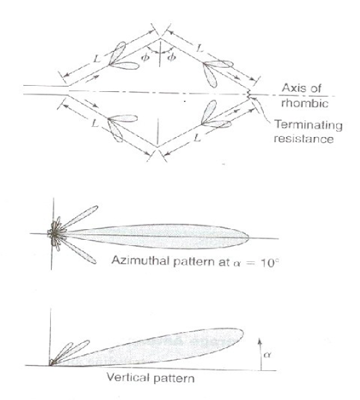
The rhombic antenna is as shown in fig . It consists of four wires in the form of a parallelogram in the horizontal plane above the earth the length of the wire is 2λ to 10λ.

For transmission purpose the radio frequency energy is fed through a balanced line at one end and the resistor at the other end. In free space the maximum gain is along the main axis and the polarization horizontal.

The antenna could be used for both transmission and reception. Because of its simplicity it is a very popular antenna for HF transmission.

Each wire produces a main beam of radiation and a number of side lobes.  The design of rhombic antenna consists of the determination of the three factors, the length L, the tilt angle $ and the height h.

The earth serves to deflect the main beam upward at some angle of  elevation. Combining with the earth plane the antenna produces a vertical pattern with an angle of elevation α.


Advantages :

• It is a wideband antenna.

• It is a high gain antenna and the required angle of equation of main lobe be obtained.

• Design and structure are simple.

• Input impedance is constant for a range of frequency.


Disadvantages :

• As terminating resistance is used efficiency is less.

• The width of the main lobe changes with frequency.


---------------------------
Article by
St.Mary's Group
ECE Dept.
Microstrip Antenna

Microstrip Antenna :


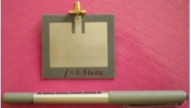
It is also called “patch antennas” as shown in figure.

▪ One of the most useful antennas at microwave frequencies (f  > 1 GHz).

▪ It consists of a metal “patch” on top of a grounded dielectric substrate.

The patch may be in a variety of shapes, but rectangular and circular are the most common

Advantages of Microstrip Antennas:

➢ Easy to fabricate (use etching and photolithography).

➢ Easy to feed (coaxial cable, Microstrip line, etc.) .

➢ Easy to use in an array or incorporate with other Microstrip circuit elements.

➢ Patterns are somewhat hemispherical, with a moderate directivity (about 6-8 dB is typical).

➢ Light weight, smaller size and lesser volume


Disadvantages of Microstrip Antennas:

➢ Low bandwidth

➢ Low efficiency

➢ Low gain


------------------
Article by
St.Mary's Group
ECE Dept.

Antenna Arrays

Antenna Arrays :

Antennas with a given radiation pattern may be arranged in a pattern line, circle, plane, etc.) to yield a different radiation  pattern.

Antenna array - a configuration of multiple antennas (elements) arranged to achieve a given radiation pattern.

Simple antennas can be combined to achieve desired directional effects.Individual antennas are called elements and the combination is an array

Types of Arrays

1. Linear array - antenna elements arranged along a straight  line.

2. Circular array - antenna elements arranged around a circular ring.

3. Planar array - antenna elements arranged over some planar surface (example - rectangular array).

4. Conformal array - antenna elements arranged to conform two some non-planar surface (such as an aircraft skin).

Design Principles of Arrays

There are several array design variables which can be changed to achieve the overall array pattern design.

Array Design Variables

1. General array shape (linear, circular,planar)

2. Element spacing.

3. Element excitation amplitude.

4. Element excitation phase.

5. Patterns of array elements.

Types of Arrays

• Broadside: maximum radiation at right angles to main axis of antenna

• End-fire: maximum radiation along the main axis of  antenna

• Phased: all elements connected to source

• Parasitic: some elements not connected to source

• They re-radiate power from other elements


----------------------------
Article by
St.Mary's Group
ECE Dept.

Antenna Field Zones

Antenna Field Zones :

The space surrounding the antenna is divided into three regions according to the predominant field behaviour. The boundaries between the regions are not distinct and the field behaviour changes gradually as these boundaries are crossed. In this course, we are mostly concerned with the far-field characteristics of the antennas.

1. Reactive near-field region : This is the region immediately surrounding the antenna, where the reactive field dominates. For most antennas, it is assumed that this region is a sphere with the antenna at its centre

2. Radiating near-field (Fresnel) region : This is an intermediate region between the reactive near-field region and the far-field region, where the radiation field is more significant but the angular field distribution is still dependent on the distance from the antenna.

3. Far-field (Fraunhofer) region : Here r >> D and r >> λ

The angular field distribution does not depend on the distance from the source any more, i.e., the far-field pattern is already well established.


--------------------------

Article by
St.Mary's Group
ECE Dept.

Sunday 19 April 2015

About St.Mary's

St. Mary's Group of Institution Hyderabad was conceived by visionary leader Rev. K.V.K Rao. In the 1996, his vision gave raise to Joseph Sriharsha & Mary Indraja educational society, which currently has a strong foothold of 28 institutions offering programs to student community by providing quality education to urban, semi-urban & rural students of National & International. With 18 years of Academic Excellence in Technical Education it has an enormous student base of 17,000 students from 28 states and 24 countries. It has a standard of on par excellence with ISO 9001 : 2000 Certificate.

The group offers various courses like B.Tech, B. Pharma, B.Ed, Polytechnic, M.Tech, MCA, MBA, M. Pharma, and PGDM which is approved by ACITE, Programs Accredited by NBA and affiliated to JNTUH, JNTUK, OU, ANU & WBUT. The group has institutions at Hyderabad, Guntur, Kolkata and Prakasham.

St Mary's Group of Institutions, Hyderabad is well articulated campus located on the outskirts of Hyderabad city at Deshmukhi (v) on Vijayawada highway near Ramoji film city behind Mount Opera. The college is located amidst sprawling and greenery between the mountains and concrete laid approach roads within the campus with a congenial atmosphere for learning. The premises spread over 120 acres of land has open spaces like lawns, gardens, seating areas, supplement the grandeur of the environment and provide calm & peaceful atmosphere to conduct academic & research pursuits. St. Mary's is the First College of approved by AICTE for foreignstudent's admissions about 300 International students are pursuing various Technical Courses. It is only group to admit over 500 students every year from different States of India. The strength of St. Mary's is highly qualified and effective doctorate Faculty with rich Academic & Research experience.